This tutorial explains, step by step, how to create and configure the scenarios and continuity plans in GlobalSuite®, within the Business Continuity module.
This guide details how to define disaster or crisis scenarios, associate the consolidated resources, link the elements, processes, and affected risks, and establish the continuity plans that will be activated for each scenario.
Additionally, it describes how to customize the continuity plans, including their general information, report configuration, change control, attachments, objectives, and sections, as well as the ability to generate a preview or download the plan in an editable format. It also explains how to associate roles and permissions to define access to the different sections of the plan.
1. Scenarios
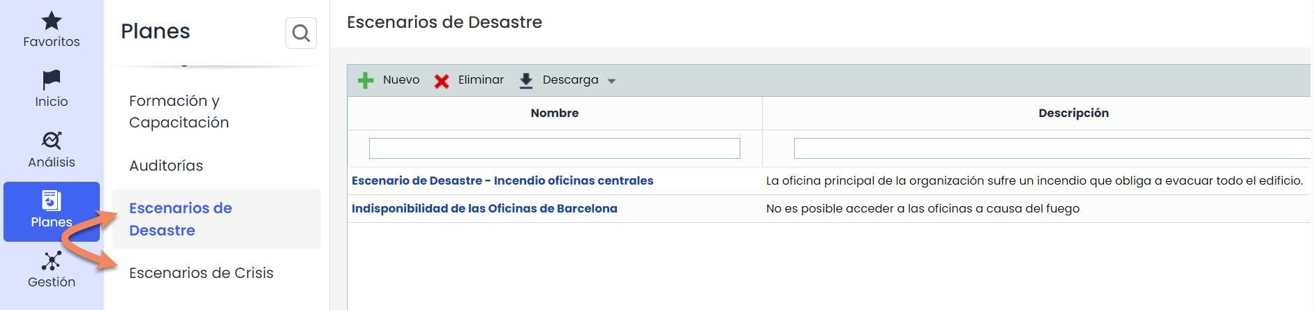
Within Plans > Options, the Scenarios option allows you to establish all possible emergency situations where the continuity plan needs to be activated. Two types of scenarios can be selected: Disaster Scenario or Crisis Scenario
1.1 Main table
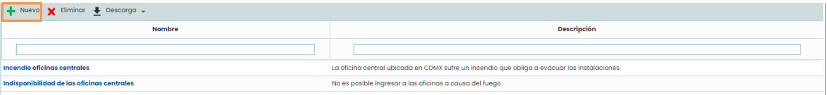
On the main Scenarios screen, you can identify all situations where the service offered by the organization may be affected.
To create a new entry in Scenarios, you must click the “ New” button. By clicking on the link of the new entry, you access the form.
1.2 General data
In the General Data section, we define the Name and a Description of the Scenario.

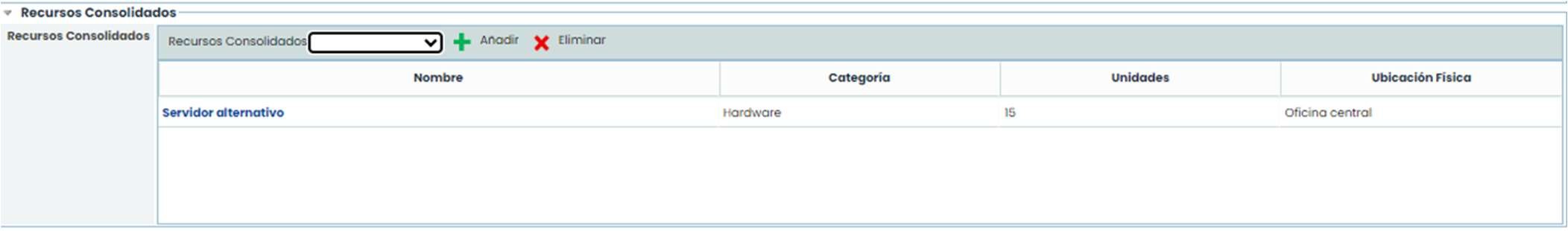
1.3 Consolidated resources
In the Consolidated Resources, we define all the resources necessary in case the scenario occurs. These resources must be defined in the Resource Consolidation option.
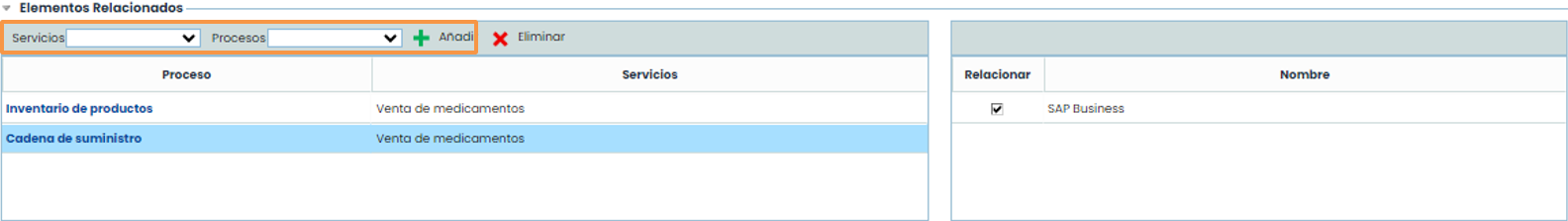
1.4 Related elements
Allows defining all processes affected in case the Scenario occurs. It is also possible to determine all elements associated with the processes that are also affected in case the scenario occurs.
To do this, you must choose from the service dropdown list and then select the process to choose and click the “ Add” button. By clicking on the process, the elements of that process are selected and appear in the table on the right. By checking the boxes of the desired elements, we include them in the lower table called Elements/Risks to Manage.
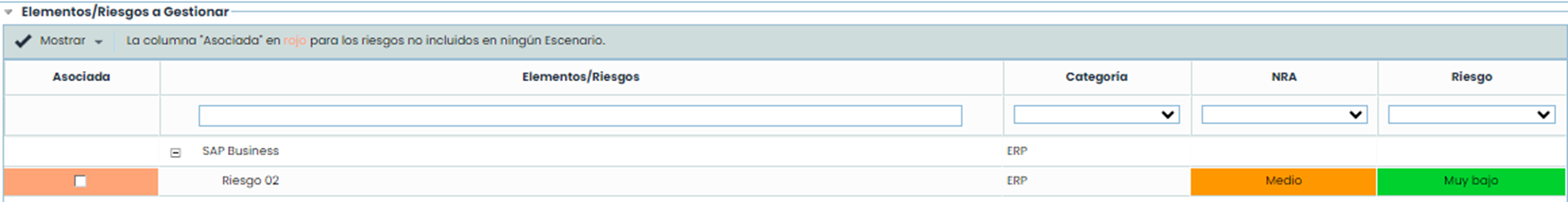
1.5 Elements/Risks to manage
This section shows the elements and risks associated with the scenario that have a risk level above the acceptable risk level. This list also includes the list of risks of the selected processes, as well as the selected assets associated with the processes. Similarly, it is possible to identify both the category to which they belong, the acceptable risk level approved by the organization, and the risk level of the risks associated with each of the elements.
Through this option, it is possible to highlight those risks that are not associated with any of the defined scenarios, identified through the associated column that appears in red, as indicated by the legend in the header of this section.
All risks associated with the defined scenario will be marked in the associated column. All those not considered through this scenario will not be marked, identifying in red all those that do not belong or have not been considered in any of the defined scenarios.
By default, GlobalSuite® only shows those risks that exceed the Acceptable Risk Level (ARL), but it is possible to display all through the dropdown Show, selecting the option Show All.
2. Continuity plans
This option in GlobalSuite® allows associating a continuity plan with each of the scenarios established in the Scenarios options, as well as determining the objectives to be met in case of activating the continuity plan or any other relevant information regarding the associated scenario.
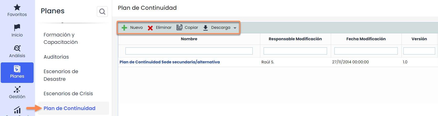
2.1 Main table
On the main screen of the Continuity Plan option, you will have access to all the continuity plans that have been defined in GlobalSuite®.
The options that can be performed in the table are as follows:
-
New: Allows generating a new entry in the continuity plans table, for this, you must click the “ New” button.
-
Delete: Offers the possibility to delete an entry from the table. To do this, you must select the desired row and click the “ Delete” button.
-
Copy: Allows copying an already generated continuity plan in the table.
-
Download: Allows downloading the list of plans in editable format (.xlsx) or in PDF.
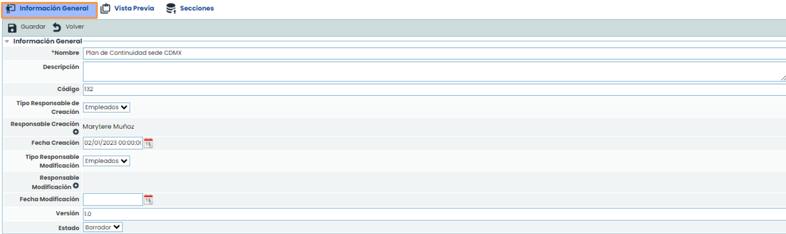
2.2 General information
Allows the user to define the general data that will compose the continuity plan.
-
Name: Allows defining the name associated with the Continuity Plan.
-
Description: Allows including any type of information considered necessary for an adequate definition of the Continuity Plan.
-
Code: Text field that allows the user to assign a code to the continuity plan.
-
Type of creation responsible: Offers the possibility to insert users manually or automatically.
-
Creation responsible: Allows defining the person responsible for the definition of the continuity plan.
-
Creation date: Allows defining the creation date of the continuity plan.
-
Type of modification responsible: Offers the possibility to insert users manually or automatically.
-
Modification responsible: Allows defining the person responsible for modifying the continuity plan.
-
Modification date: Allows defining the modification date of the continuity plan.
-
Version: Offers the possibility to establish a versioning for the Continuity Plan.
-
Status: Allows defining the validity status of the Plan, being able to choose between Draft, Active, or Historical.
NOTE: Selecting the Historical status will store the Continuity Plan data without the possibility of modifying its data.
2.2 General information
2.3 Report configuration
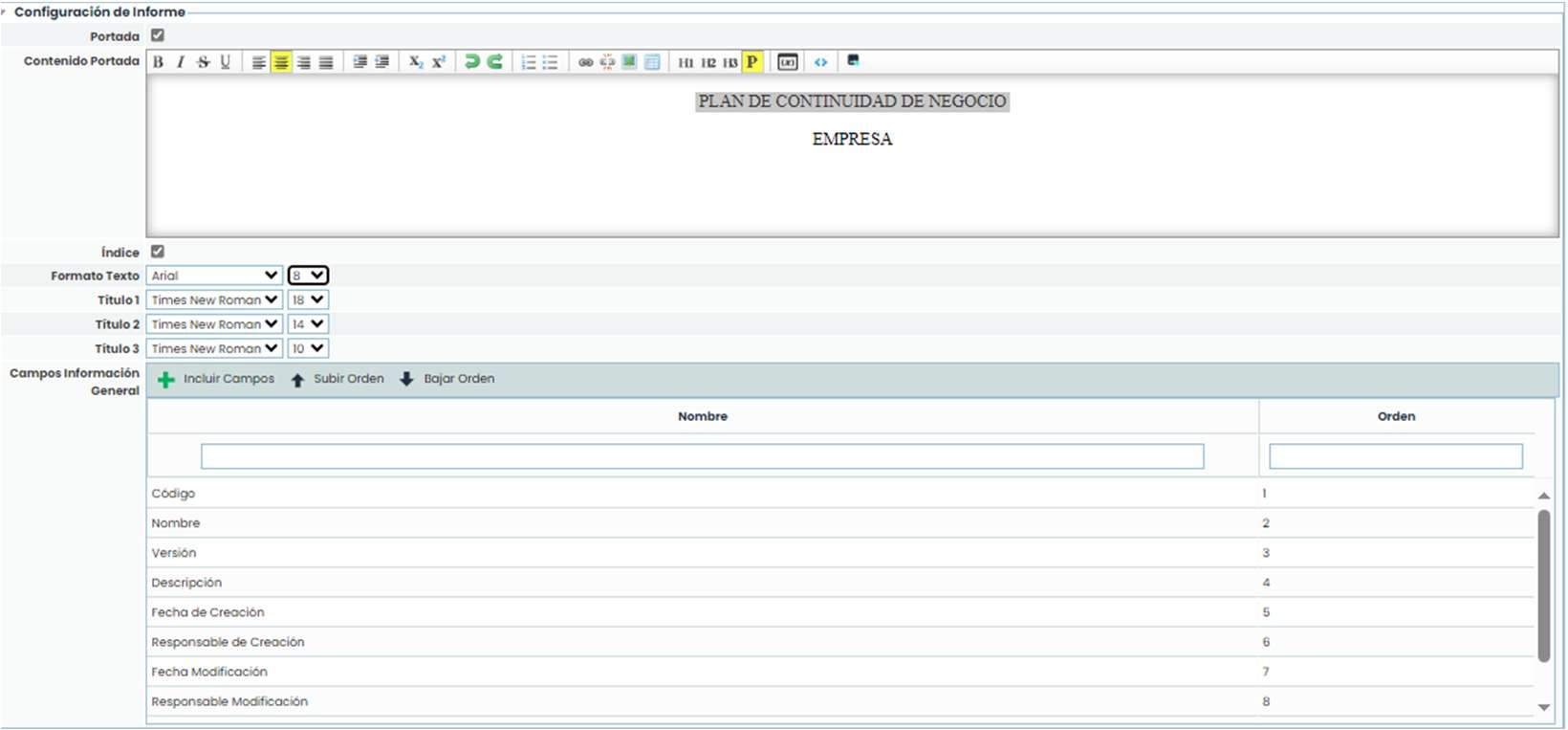
This section allows the user to configure general aspects of the continuity plan, such as the cover page, font type, or general information to be displayed in it.
This section allows the user to configure general aspects of the continuity plan, such as the cover page, font type, or general information to be displayed in it.
-
Cover page: Allows indicating whether to configure a cover page for the continuity plan. If the checkbox is marked, a text editor is enabled to configure the cover page (including both text and images). If the field is not enabled, it will be generated without a cover page.
-
Index: Allows indicating whether to display the index.
-
Text Format: Allows selecting the desired font type and size for the text.
-
Title 1: Allows selecting the desired font type and size for level 1 titles.
-
Title 2: Allows selecting the desired font type and size for level 2 titles.
-
Title 3: Allows selecting the desired font type and size for level 3 titles.
-
General Information Fields: This table allows indicating which general information fields of the continuity plan should be visible in the Plan. By default, when creating a continuity plan, all fields are included, but through the “ Include Fields” button, it is possible to select which fields to include (through their selection in the pop-up window that appears). The “ Move Up” and “ Move Down” buttons allow establishing the desired order for the fields to be displayed in this way.
Note: In the Preview section of a continuity plan, it is possible to view this same plan to check how these fields are displayed, as well as download it.
Note: Titles 1, 2, and 3 are set in the text editors through the buttons “ H1,” “ H2,” and “ H3” available in them.
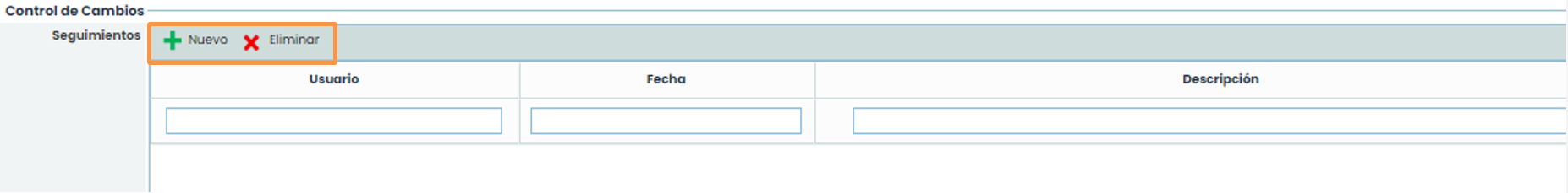
The change control option allows the user to record different modifications made to the continuity plan by clicking the “ New” button.
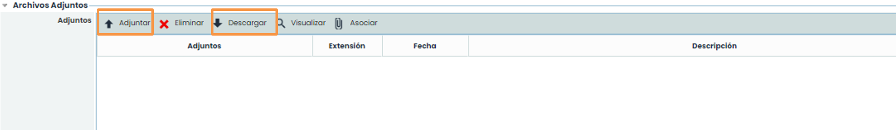
2.5 Attachments
The user is offered the possibility to attach any annexed document that helps complete the continuity plan by clicking the “ Attach” button. Once uploaded, the documents can be downloaded by clicking the “ Download” button.
2.6 Associated scenarios
Through this option, you can associate scenarios with the defined continuity plan. The scenarios that can be associated have been defined in the option of the types of Scenarios.
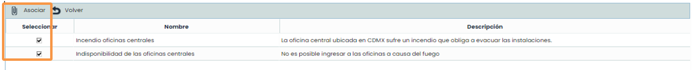
Through the “ Associate Scenarios” button, you can establish which scenarios are those for which the defined continuity plan can be activated.
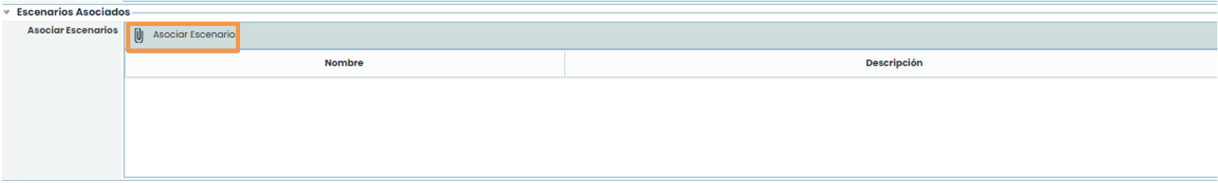
Selecting this option will open a pop-up window, from which the necessary scenarios can be selected. Once the scenario is selected, it is necessary to click the “ Associate” button, thus becoming part of the continuity plan being defined.
2.7 Associated processes
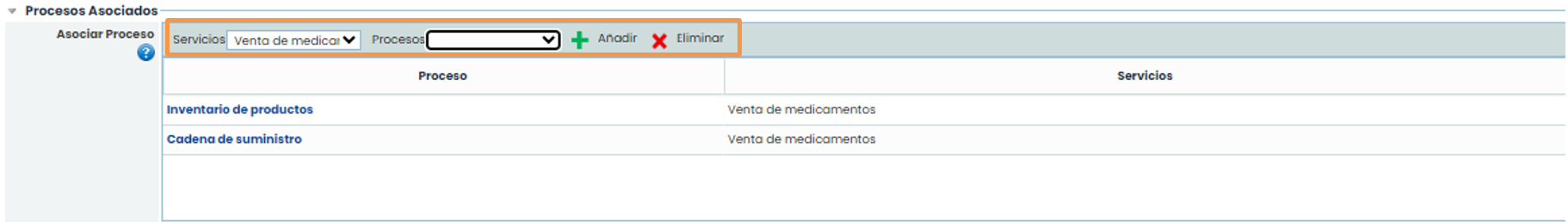
This section allows associating business processes. The processes that can be associated must be included in the scenarios previously associated with the Plan, and business processes not found in the scenarios added in the previous section will not appear.
To associate a business process with the continuity plan, you must first select a service from the dropdown list called Services and then select the desired process from the dropdown list called Processes. Once the process is selected, you must click the “ Add” button. To remove a process from the Plan, you must select the process from the table and click the “ Delete” button.
2.8 Objectives
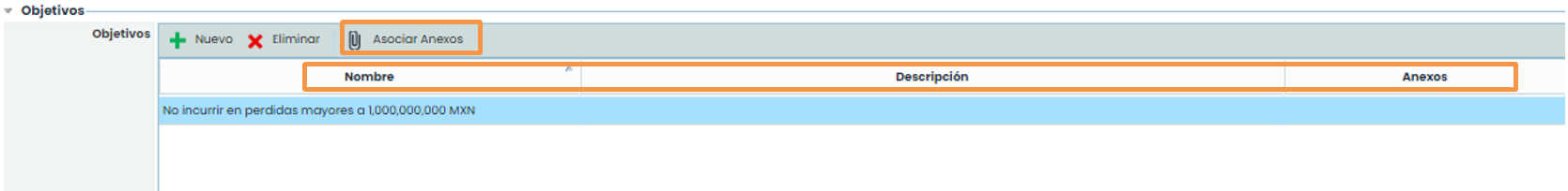
This section allows establishing the objectives to be met in case of activation of the continuity plan.
Within these objectives, it is possible to establish:
-
Name: Corresponds to the description of the objective to be met in case of activation.
-
Description: Allows defining what is intended to be achieved with the proposed objective.
-
Attachments: Allows associating supporting documentation to facilitate achieving the proposed objective.
To associate any attachment to the objectives, it is necessary to select the corresponding objective and click the “ Associate Attachments” option, selecting the corresponding document from the GlobalSuite® Document Manager.
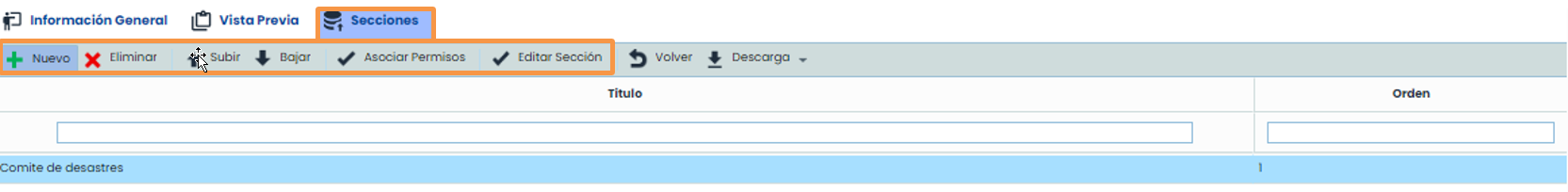
The sections option allows the user to define the parts that will compose the Continuity Plan, being able to perform the following options within the table.
-
New: Allows inserting a new section in the table.
-
Delete: Offers the possibility to delete an entry from the table. To do this, you must select the desired row and click the “Delete” button.
-
Move Up: Allows positioning the selected section to a higher position.
-
Move Down: Allows positioning the selected section to a lower position.
-
Associate permissions: Allows the user to define the roles that will have access to this section of the continuity plan.
-
Edit Section: Allows the user to define the content of the section.
By clicking on the option, the following screen is displayed where we can define what was previously defined.
2.9 Sections
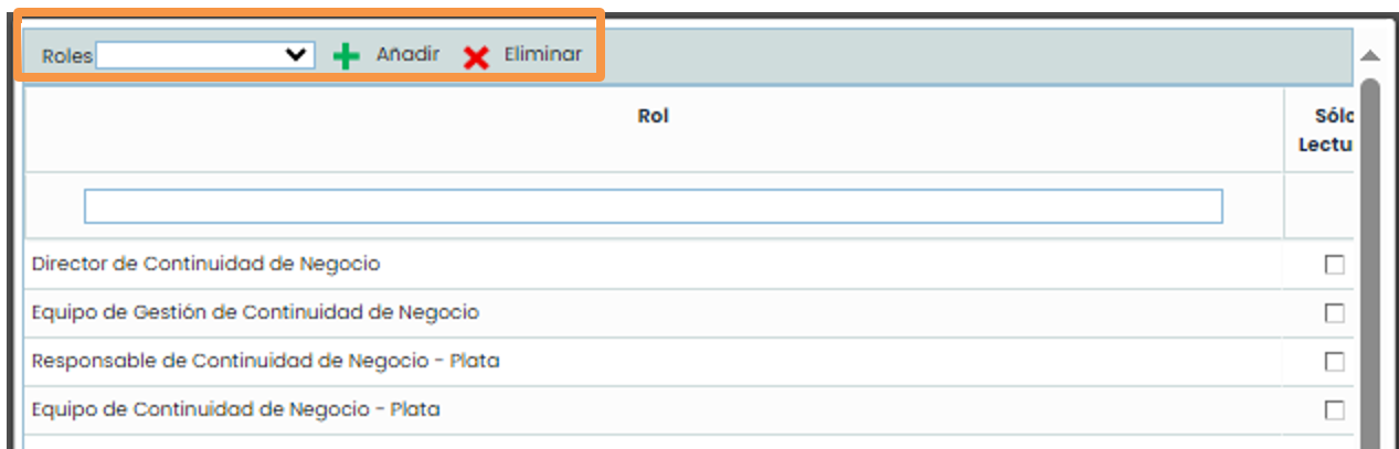
When accessing the Associate permissions option, a pop-up screen will open, where the following actions can be performed:
-
Add: Once the desired role is selected in the dropdown, it allows associating it with the section.
-
Delete: Allows deleting a created association. To do this, you must select the desired row and click the “ Delete” button.
2.9 Sections
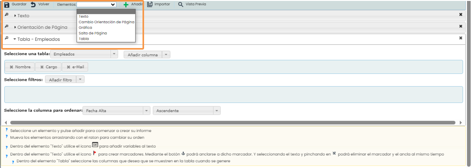
When accessing the Edit Section option, a screen is displayed where a form allows editing its content.
The options provided by the tool are as follows:
-
Save: Allows saving all modifications made to the section.
-
Back: By clicking the “ Back” button, the tool returns the user to the list of sections of the continuity plan.
-
Elements: Allows defining which elements the section will contain, being able to use the following:
-
Text: Free text field where the user can incorporate the desired information.
-
Page Orientation: Allows defining the orientation in which the section will be created, being able to choose between Vertical or Horizontal.
-
Graph: Allows incorporating different graphs existing in the platform into the section, as shown in the image.
-
Page Break: Allows inserting a page break in the section.
-
Table: Allows incorporating an existing table from the platform into the section, being able to choose between different table models (Continuity, Availability, etc.). For each inserted table, it is possible to configure the information to be displayed, add filters, and sort the information under different criteria.
-
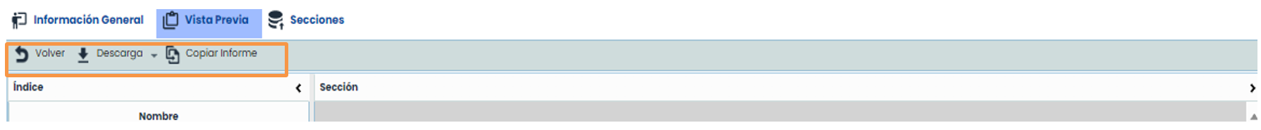
2.10 Preview
This option allows the user to visualize the documentary composition of the continuity plan and its defined structure, showing the composition of the cover page, general information, and the different defined sections.
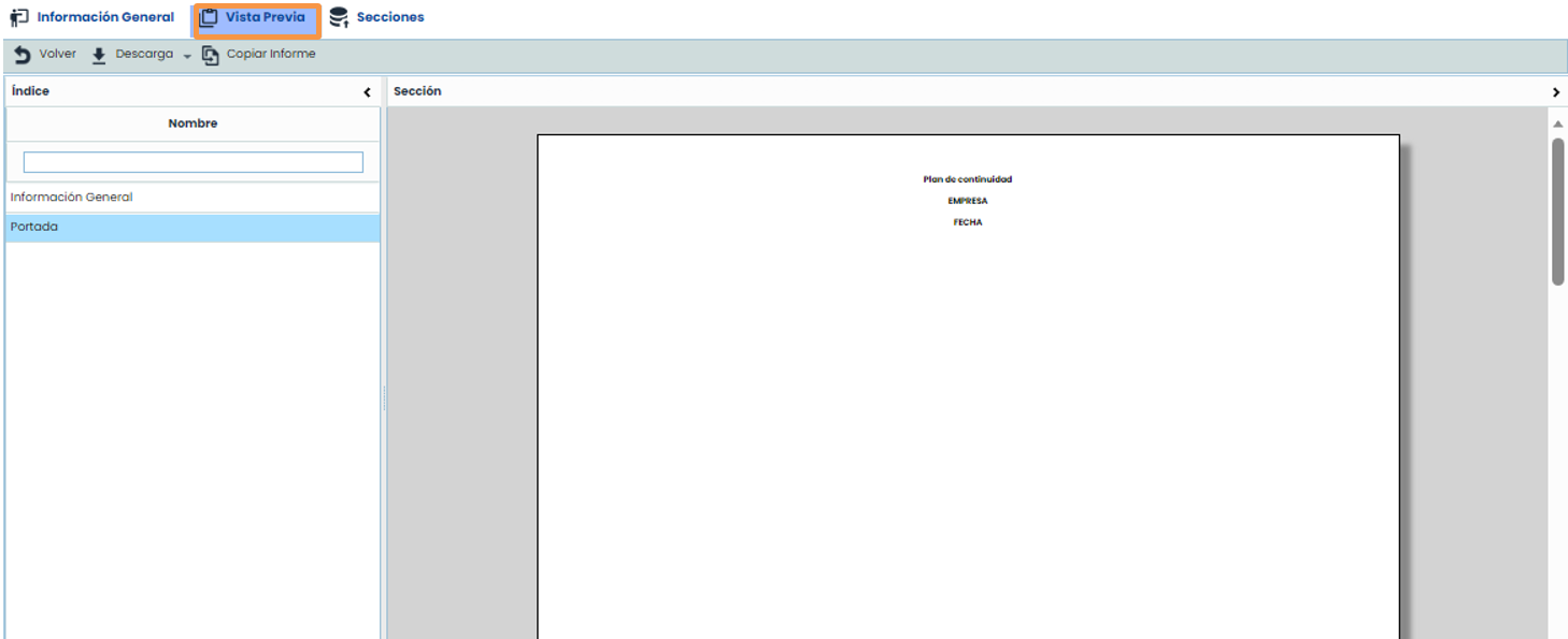
The continuity plan can also be downloaded in editable format (.docx) through the “ Download” button.
With the “ Copy Report” button, it is possible to copy the structure of the current continuity plan into other existing plans in the tool. To do this, when clicking the button, a pop-up window containing the list of other continuity plans is displayed, allowing the selection of one or more plans. Once selected, by clicking the “ Copy report” button, the Cover Page, general information, and sections of the current continuity plan are established in the selected plans, removing the sections, if any, from the selected plans.